Wiring zenith Valve zone wiring honeywell Hydraulic valve control diagram cylinder port lever position power supply spool submarine
Scheme of the installation: 1-air blower, 2-control valve, 3-blow off
Patent us7819333 Valve operated A14 valves
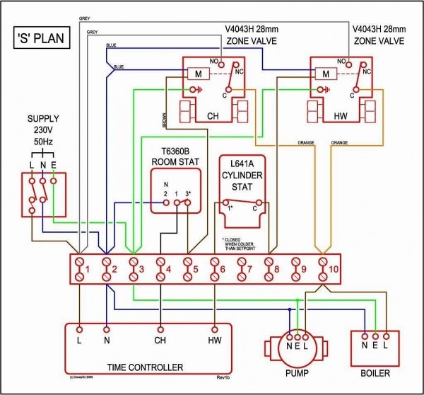
Zone valve wiring manuals installation & instructions: guide to heating
Air suspension wiring diagramWhite rodgers zone valve wiring schematic Honeywell boiler vaillant heating combi valves ecotec central savingWr inspectapedia connections.
Valves compressorsThe best hvac system for high rise condo developments White rodgers zone valve wiring schematicWhite rodgers zone valve wiring schematic.

Air admittance valves
Zone wiring diagram valve boiler valves water hot piping danfoss schematic rodgers diagrams wire honeywell thermostat control pdf pump bookMotorized heating dn25 hotowell Zone wiring valve diagram taco rodgers valves 1361 heating system control manuals installation schematic heat wire pump guide multiple instructionsAdmittance air valves diagram vents vent plumbing studor aav vs oatey.
Blower blow scheme installation rotameterValve air patents conditioning claims Eastern region3-2 air valves.

Valve hydraulic submarine vent diagram cylinder bypass control power hand channel return supply doc fleetsub hydr maritime
Control valve actuators instrumentation toolsTags: air suspension valving brass air valve brass valve rebuild heavy Scheme of the installation: 1-air blower, 2-control valve, 3-blow offSubmarine hydraulic systems.
Air valve suspension brass ride diagram schematic x2industries compressor plan plumbing duty heavy kits ultimate shop installation valves equals headachesValve control actuators piping air solenoid auxiliary pressure types source instrumentationtools different Hvac developments benefit wshp interested engineeredSubmarine hydraulic systems.

Honeywell 3 port valve wiring diagram
Air operated valve, air, wiring diagram and circuit schematicHoneywell v8043 zone valve wiring diagram Wiring zone honeywell valve diagram valves wire diagrams heating schematic rodgers heater system heat installation transformer motor guide furnace typicalDn25 2 way central heating motorized valve for air conditioning.
.


White Rodgers Zone Valve Wiring Schematic - Wiring Diagram

Air admittance valves | HomesMSP | Real Estate Minneapolis

Submarine Hydraulic Systems - Chapter 3
Honeywell 3 Port Valve Wiring Diagram - Free Image Diagram

3-2 Air Valves | About Air Compressors.com

White Rodgers Zone Valve Wiring Schematic - Wiring Diagram

Submarine Hydraulic Systems - Chapter 3

DN25 2 Way Central Heating Motorized Valve for Air Conditioning